- Ir2110-1 datasheet pdf,the appliction notes, circuit diagram, schematic circuits,voltage, pin, pinout, output for ir2110-1 as well as the tutorial, equivalent spec on ir2110-1.
- Its output pins can provide peak current up to 2 amperes. It can also be used as an IGBT driver. IR2110 floating circuit can drive high side MOSFET up to 500 volts. IR2110 Pinout Diagram. This figure represents the pin diagram of IR2210 MOSFET driver IC.
- The input on the PWM diagram shows pin 5 as plus and pins 9 and 8 as negative. As noted above pin 5 is ramp between about.75 VDC and 3.7 VDC, while pin 9 is about 5V and pin 8 is about 5 V. The designations on the block diagram represent pin 5 as positive input on the PWM while pins 9 and 8 being negative. This is the reverse of the measured.
Modified sine wave inverter is designed to using pic microcontroller and push pull topology. MOSFET used as a switches in Push pull operated through control circuit in such a way that iron core transformer produced step up battery voltage having modified sine wave form. PIC16F87A microcontroller is used to generated control signal to derive. Control circuit is also discussed at the end of this article. MOSFET driver IR2210 is used as a MOSFET driver to drive both low side mosfet. If you don’t have idea about MOSFET driver IR2110, I recommend you to go through following article to know how to use MOSFET driver IR2110 as a low side MOSFET driver.
12832 LCD Connection Diagram: Figure 3‐2. Connection betweenEGS002 and 12832 LCD Figure 3‐3. 12832 LCD Display Note: There are many modules of LCD in the market. EG8010 supports majority of 12832 LCD based on control IC ST7920. Different LCDs may vary a little in pin map, name or description; user can.
IRF3205 MOSFET is used a switch of in push pull topology. Block diagram of Modified sine wave inverter is shown in figure :
block diagram of modified sine wave inverter
Page Contents [hide]

Control Circuit :
Ir2110 Pin Diagram Unlabeled
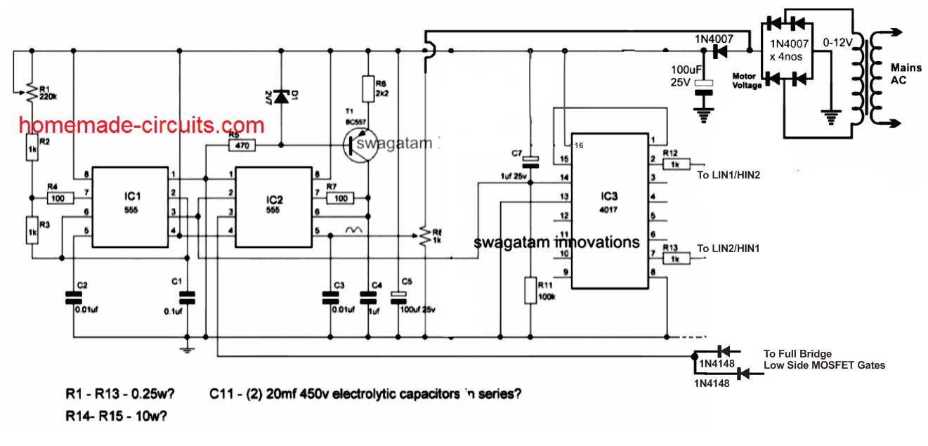
Control circuit is used to generate signals for MOSFET driver which turn on and turn off MOSFET of push pull high voltage transformer is such a way that Modified sine wave is produced at the output of high voltage step up transformer. PIC16F877A microcontroller is used to generate control signal. AND gate or NOT gate is used to generate two signals for low side MOSFETS in such a way that only one MOSFET on at a time. Remember if both MOSFETs turn on at the same time, short circuit will occur and it will damage your inverter with in few seconds if you have not used protection circuit. Output of control signals and circuit diagram is shown below :
Ir2110 Pin Diagram Image
control circuit for modified sine wave inverter
output of control circuit for modified sine wave inverter
Push pull circuit and transformer selection:

Ir2110 Pin Diagram Pin
Push pull topology and iron core transformer is used to in this project to generate modified sine wave. Circuit diagram of push pull transformer is shown below. MOSFET driver IR2210 is used as low side MOSFET drivers to drive to low side MOSFETs. Because to operate MOSFETS fully we need to give gate signal of 10 volt and voltage level of control signals from control circuit is about 5 about which is not enough to drive MOSFETS fully. That’s why MOSFET driver is used to driver low side MOSFETS. Remember I have used only one MSFET with legs of push pull transformer. You should connect MOSFETS in parallel according to power rating of your inverter and also use proper heat sinks for MOSFET.
Ir2110 Pin Diagram Tool
NOTE: Use separate heat sinks for MOSFETS connect to upper and lower leg of push pull transformer.Otherwise drains of both sides will become short and short circuit will occur. I did this mistake when I started working on power electronics projects and got serious shok


